

Our Products
-
PU TUBES
-

ADHIKARI PU COILED HOSES
-
ADHIKARI PU COILED HOSE
-
ADHIKARI ROUND CORD
-
11744-5239125.jpg)
PU ROUND CORD
-
 coting -500x500.jpg)
PU ROUND CORD
-
APSOO PU TUBING ROLLS
-
APSOO PU TUBING ROLLS
-
11744-5239125.jpg)
PU ROUND CORD
-
ADHIKARI PU COILEDHOSE
-
ADHIKAI PU COILED
-
ADHIKARI PU COILED HOSE
-
APSOO PU TUBING ROLLS
-
APSOO PU TUBING ROLLS
-
APSOO PU COILED HOUSE
-

NYLON TUBING ROLLS
-
PU Round Cord
-
PU Coiled House
-
PU Tubing Rolls
-
PU Round Cord
-
COOLANT PIPE
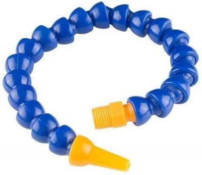 A "pneumatic coolant pipe" refers to a flexible hose or pipe specifically designed to carry coolant fluid under pressure, typically used in industrial machinery where compressed air is utilized to deliver the coolant to the cutting or machining area; essentially, it's a hose that uses air pressure to efficiently transport coolant fluid.Key points about pneumatic coolant pipes:
-
Delivers coolant fluid to the desired location using compressed air pressure, enabling precise control over the coolant flow.
-
Usually made from flexible plastic or rubber materials that can withstand pressure and resist chemicals present in coolants.
-
Commonly used in CNC machines, milling machines, drilling rigs, and other industrial equipment where precise coolant delivery is crucial.
Feedback Form x -
-
AIR SILENCER
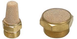 An air silencer, also known as a pneumatic silencer or muffler, is a device that reduces the noise made when compressed air is released. They are often used in machines and are an important part of pneumatic systems.How do air silencers work?
- Reduce noise: Air silencers reduce the noise of the air being released by increasing the surface area of the exhaust. This helps to diffuse the pressure of the air, which reduces the turbulence and velocity of the escaping air.
- Control airflow: Air silencers can also control the speed of the air being released.
- Protect valves: Air silencers can keep suspended solids out of the valve, which helps to protect it.
Where are air silencers used?- Air silencers are often used with valves, manifolds, cylinders, compressors, and fittings.
- They are important to make sure that employees are not exposed to harmful noise.
MaterialsAir silencers can be made from a variety of materials, including plastic, brass, and porous aluminum.
Feedback Form x -
FILTER REGULATOR LUBRICATOR
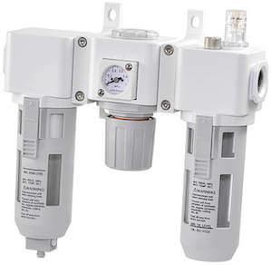 A filter regulator lubricator (FRL) is a unit that cleans, regulates, and lubricates compressed air. It's used in pneumatic systems to power tools and other equipment.How does an FRL work?
- Filter: Removes water, dirt, and other particles from the air
- Regulator: Controls the air pressure
- Lubricator: Lubricates pneumatic components to extend their lifespan
Applications- Pneumatic tools: Ensures the required airflow pressure and air quality
- HVAC systems: Delivers clean air to the workplace
- Industrial equipment: Provides clean, regulated air to protect employees and applications
Benefits- Increases performance: Reduces maintenance from pipe scale, water condensate, and burnt compressor oil
- Prevents downtime: Prevents contamination that can cause downtime
- Improves safety: Protects employees from harmful effects of unfiltered air
When to install an FRL- When using pneumatic tools and equipment
- When installing an HVAC system
- When delivering clean air to the workplace
- When requiring compliance with air quality standards
Feedback Form x -
hose reel
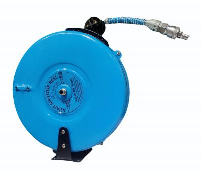
An air hose reel in India is a specialized mechanical device designed to safely store, manage, and dispense air hoses used in various industrial, commercial, and automotive applications. It is a valuable tool for businesses and industries in India where a reliable and controlled supply of compressed air is essential for pneumatic tools, equipment, and other pneumatic applications.
Description:
The air hose reel available in India is engineered with durability, safety, and convenience in mind. Its key components and features may include:
1. Sturdy Construction: The body of the air hose reel is typically made from high-quality materials, such as steel or corrosion-resistant materials like stainless steel or polypropylene, ensuring it can withstand the demands of Indian industrial environments and resist damage from frequent use and exposure to the elements.
2. Compressed Air Hose: The hose used with the air reel is specifically designed to handle high-pressure compressed air, made from durable materials that can withstand the pressure and temperature associated with compressed air systems.
3. Automatic Retractable Mechanism: Many modern air hose reels in India are equipped with an automatic retractable mechanism that allows the hose to be easily and neatly wound back onto the reel after use. This feature minimizes tangling and reduces the risk of accidents during hose handling.
4. Swivel Mounting Bracket: A swivel mounting bracket enables the hose reel to rotate smoothly, making it easier to access different areas without twisting or tangling the hose.
5. Adjustable Hose Stopper: Some models have an adjustable hose stopper, allowing users to set a specific length of the extended hose and maintain consistency during compressed air operations.
6. Locking Mechanism: To secure the hose at a desired length during air dispensing and prevent unauthorized use, many air hose reels in India are equipped with a locking mechanism.
7. Hose Length and Diameter: Air hose reels in India come in various lengths and diameters to accommodate different applications and compressed air system requirements.
8. Hose End Fittings: The hose may come with standard fittings such as quick-connect couplings or other connectors compatible with compressed air systems commonly used in India.
9. Pressure Rating: The hose and reel are rated to handle specific pressure levels, ensuring safe and reliable operation within the intended range.
10. Versatile Mounting Options: Air hose reels in India can be wall-mounted, ceiling-mounted, or floor-mounted, offering flexibility in installation and positioning within the workspace.
Benefits of Air Hose Reels in India:
1. Safety: The automatic retractable mechanism and organized hose storage reduce the risk of accidents, spills, and tripping hazards in the workplace.
2. Efficiency: The easy accessibility of hoses and controlled air flow enhance efficiency and productivity during compressed air operations.
3. Cleanliness: The hose reel's containment system prevents kinks, damage, and wear on the hose, maintaining a clean and organized workspace.
4. Durability: The use of high-quality materials ensures the air hose reel's longevity, reducing maintenance requirements and extending its service life.
In conclusion, an air hose reel in India is a crucial tool for industries and businesses that rely on compressed air systems. It provides a safe, efficient, and organized solution for handling air hoses, contributing to a more productive and efficient work environment in India.
Feedback Form x -
Foot paddle
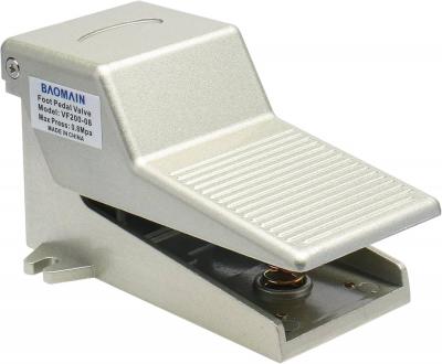
Pneumatic foot pedal valves are significant components of air-powered equipment. You might not see them often, but they’re used in many industries, from factories to medical settings, to make work easier and safer. That is why, let us first address what pneumatic foot pedal valves accomplish, how they function, as well as what types of pneumatic foot pedal valves are available. So, keep scrolling to explore more!
Working Principle And Types of Pneumatic Foot Pedal .
1) A brief overview of Pneumatic foot pedal valves
“As the name suggests it is a valve that enables you to control the flow of air over a particular machine or equipment with your own foot.”
Because an air compressor does all the work, a valve of this kind can be described as a “pneumatic” valve (pneuma is the Greek word for air). By turning the valve with your foot, you’re able to direct air through various appliances such as air motors, which is somewhat similar to opening a tap in order to let water run out.
Working Principle And Types of Pneumatic Foot Pedal Valves 9
They are not only primarily utilized in the automotive and construction sectors but also in the healthcare and other industries because of their reliability, cleanliness, and ease of use. You can utilize the equipment without using your hands, so, you can do other critical processes at the same time.
2) What is the working principle of a pneumatic foot pedal valve?
When working with a machine, you will notice that there are functions like turning it on or off or adjusting the speed of it. The appropriate method in this case would be to use your foot rather than your hand to operate the pedal valve. So, let’s discuss how you can do this!
Step#1) Compressed air supply:
● The valve is attached to an air supply. This air supply comes from a compressor attached to the machine.
Step#2) Pedal Actuation:
● Now, when you employ the pedal, it initiates the mechanism within the valve.
Step#3) Air Flow Control:
● The valve either moves or repositions itself, permitting compressed air to proceed in a variety of directions throughout the machine, or alternatively, cutting it off entirely.
Working Principle And Types of Pneumatic Foot Pedal Valves 10
Step#4) Return Mechanism:
● After you free your foot off the pedal, the valve moves back to its original state. The passage of air ceases or modifies in accordance.
Working Principle And Types of Pneumatic Foot Pedal Valves 11
So, in short, when the foot pedal is depressed, pressure is exercised which in turn leads to the opening of the valve and consequently provides air. Releasing the pedal ensures the valve can close thus preventing air flow from occurring. Such a simple mechanical revolution allows machines to work without any manual support.
● Common Uses: You will find 3/2-way valves in single-acting cylinders as one of the functions is to activate with air to move the piston and once the piston is in its place, the air is released. These may be mounted into any sort of presses or simple clamps.
Working Principle And Types of Pneumatic Foot Pedal Valves 12
pneumatic foot pedal switch
iii) 5/2-Way Valve
There are five ports on the valve (one for air supply, two for connecting to a cylinder, and two for exhausts) and two positions on this valve.
● Common Uses: The 5/2-way valves are mostly operated in much of double-acting cylinders where the movement is required in both directions such as robotic hand or conveyor systems where the motion of push and pull action is continuous.
pneumatic foot pedal control valve
v) 5/3-Way Valve
This valve must have five ports too, but instead of diagramming three positions including the center one for control purposes.
● Common Uses: The more sophisticated equipment you notice 5/3-way valves if there is a need to accurately stop and retain a cylinder, triggered in automated assembly facilities or positioning applications.
Working Principle And Types of Pneumatic Foot Pedal Valves 13
➔ Based on the operational mode
v) Detent Foot Pedal Valve
A detent foot pedal valve has a peculiar characteristic of locking, so the pedal remains in the same place when pressed and pushed down.
● Common Uses: Detent valves are mostly made in applications such as conveyors where to keep the machine at constant air pressure without the need to hold down a pedal.
vi) Momentary Foot Pedal Valve
A momentary foot pedal valve is a type of valve in which airflow is only activated when you press down the foot pedal. When you release the pedal the function also gets stopped.
● Common Uses: Momentary valves are ideal for applications in which air is required to be able to flow for only a certain amount of time like air-powered tools or machines that require a blast of air for some seconds.
4) Importance of Pneumatic foot pedal valves in industries
Now you may ask yourself, “Why is it even necessary to have pneumatic (air) foot pedal valves?” Well, there are a couple of significant answers to this question:
+ Hands-free work: By using your feet, you operate the machine allowing your hands to be free. This would definitely speed up the work.
+ Safety: In some cases, foot pedals work as valves for dangerous machines. In such cases, the foot acts as a middleman, as you can maintain a distance from the weapon, therefore increasing security.
+ Precision: Some work, however, requires the operator to have precise control over the amount of air that flows. This is pretty well achieved using foot valves.
+ Efficiency: These valves also enable the workers to work on machines in an efficient manner without being subjected to unnecessary disruptions or delays.
5) Final Words
In a nutshell, we can say that foot pedal air valves play a crucial role in the control of machines working with compressed air, but they are also still very basic devices. Pedals provide an easy way to accomplish work while maintaining safety. We have discussed several types of pneumatic foot pedal valves, each suited to different needs and types of equipment.
It does not matter if it is a simple or a complicated machine, they contribute towards making air-powered equipment more effective and dependable. So, if you are interested in buying sustainable and reliable pneumatic or air foot pedal valves you can contact Aps overeas.
Feedback Form x -
Tube Cutter
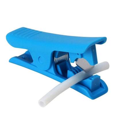
A tube cutter is an effective tool for cutting tubes to a certain length. Tube cutters and pipe cutters are often used interchangeably on tubes and pipes. However, there are a few key differences between both device types. This article explores how to use a tube cutter to cut and deburr a copper pipe and how the tool differs from a pipe cutter.
Feedback Form x -
Ball Valve
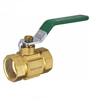
A ball valve is a flow control device which uses a hollow, perforated, and pivoting ball to control fluid flowing through it. It is open when the hole through the middle of the ball is in line with the flow inlet and closed when it is pivoted 90 degrees by the valve handle, blocking the flow.[1] The handle lies flat in alignment with the flow when open, and is perpendicular to it when closed, making for easy visual confirmation of the valve's status.[2] The shut position 1/4 turn could be in either clockwise or counter-clockwise direction.
Ball valves are durable, performing well after many cycles, and reliable, closing securely even after long periods of disuse. These qualities make them an excellent choice for shutoff and control applications, where they are often preferred to gates and globe valves, but they lack the fine control of those alternatives, in throttling applications.
The ball valve's ease of operation, repair, and versatility lend it to extensive industrial use, supporting pressures up to 1,000 bar (100 MPa; 15,000 psi) and temperatures up to 750 °F (400 °C), depending on design and materials used. Sizes typically range from 0.2 to 48 in (5 to 1200 mm). Valve bodies are made of metal, plastic, or metal with a ceramic; floating balls are often chrome plated for durability. One disadvantage of a ball valve is that when used for controlling water flow, they trap water in the center cavity while in the closed position. In the event of ambient temperatures falling below freezing point, the sides can crack due to the expansion associated with ice formation.[3] Some means of insulation or heat tape in this situation will usually prevent damage. Another option for cold climates is the "freeze tolerant ball valve". This style of ball valve incorporates a freeze plug in the side so in the event of a freeze-up, the freeze plug ruptures, acting as a 'sacrificial' fail point, allowing an easier repair. Instead of replacing the whole valve, all that is required is the fitting of a new freeze plug.[4]
For cryogenic fluids, or product that may expand inside of the ball, there is a vent drilled into the upstream side of the valve. This is referred to as a vented ball.
A ball valve should not be confused with a "ball-check valve", a type of check valve that uses a solid ball to prevent undesired backflow.
Other types of quarter-turn valves include the butterfly valve and plug valve and freeze proof ball valve.
Feedback Form x -
AIR BLOW GUN (ABG06)

An air blow gun is a device used for applications requiring compressed air like removal of debris, non-contact drying and blowing. It consists of a nozzle that is attached to the airline, which delivers a steady stream of compressed air. It is typically used in laboratories and manufacturing industries. Figure 1 is an example of a compressed air blow gun.
To choose a suitable air blow gun you first have to look at the maximum pressure that can be applied. First, it is important to check your input connection type and size to match the air compressor hose. Then, the air blow gun’s nozzle should be selected to ensure a suitable output port for your application. The output of compressed air can be constant or adjustable depending on the trigger design.
Feedback Form x -
Air cylinder
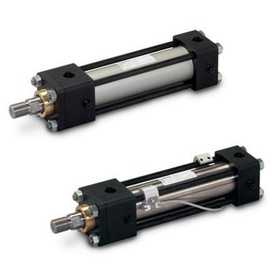
Pneumatic cylinder, also known as air cylinder, is a mechanical device which uses the power of compressed gas to produce a force in a reciprocating linear motion. Like in a hydraulic cylinder, something forces a piston to move in the desired direction.
Feedback Form x -
Quick release coupling
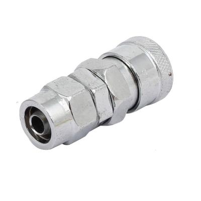
Quick release couplings are fitting are used to mate fluid lines with system equipment that requires frequent connecting and disconnecting. They are used in both pneumatic and hydraulic applications to build or discontinue the connection of a fluid pipeline.
It is well known as quick coupler, quick coupling or quick connect coupling. Quick coupling can be made of stainless steel SS316, carbon steel and brass material for practically every application contingency. The fittings size is available from 1/4” to 2”. The working pressure will be determined depending on the body size.
Feedback Form x -
Manifold
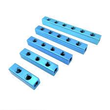
A manifold is a fluid or gas distribution system or device that serves to bring many valves into one place or a single channel into an area where many points meet. Manifold systems can range from simple supply chambers with several outlets, to multi-chambered flow control units.
Feedback Form x -
Flow Control
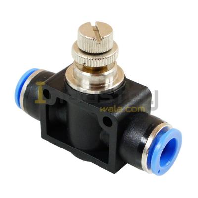
What is flow control?
Flow control is a technique used to regulate data transfer between computers or other nodes in a network. Flow control ensures that the transmitting device does not send more data to the receiving device than it can handle. If a device receives more data than it can process or store in memory at any given time, the data is lost and needs to be retransmitted.
The purpose of flow control is to throttle the amount of data transmitted to avoid overwhelming the receiver's resources. This is accomplished through a series of messages that the receiver transmits to the sender to acknowledge if frames have been received. The sender uses these messages to determine when to transmit more data. If the sender does not receive an acknowledgement (ACK), it concludes that there has been a problem with the transmission and retransmits the data.
Flow control is implemented in different ways, depending on how the sender and receiver handle messages and track data frames. There are two basic approaches to flow control: stop and wait and sliding window. The stop-and-wait approach is the simplest to implement, but it is not as efficient as sliding window, which delivers better network performance and utilizes network resources more effectively.
Stop-and-wait flow control
In the stop-and-wait approach, the sender segments the data into frames and then transmits one frame at a time to the receiver, which responds to each frame with an ACK message. This process occurs through the following steps:
- The sender transmits a data frame to the receiver.
- The sender waits for the receiver to respond.
- Upon receiving the frame, the receiver transmits an ACK to the sender.
- Upon receiving the ACK, the sender sends the next frame to the receiver and waits for the next ACK. If the sender does not receive an ACK within a defined time limit, known as a timeout, the sender retransmits the same frame.
- The process continues until the sender has finished transmitting all the data to the receiver.
Feedback Form x -
Solenoid valve
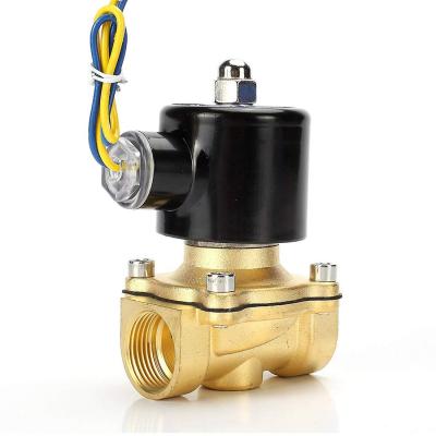
A solenoid valve is an electromechanically operated valve.
Solenoid valves differ in the characteristics of the electric current they use, the strength of the magnetic field they generate, the mechanism they use to regulate the fluid, and the type and characteristics of fluid they control. The mechanism varies from linear action, plunger-type actuators to pivoted-armature actuators and rocker actuators. The valve can use a two-port design to regulate a flow or use a three or more port design to switch flows between ports. Multiple solenoid valves can be placed together on a manifold.
Solenoid valves are the most frequently used control elements in fluidics. Their tasks are to shut off, release, dose, distribute or mix fluids. They are found in many application areas. Solenoids offer fast and safe switching, high-reliability, long service life, good medium compatibility of the materials used, low control power and compact design.
Operation
[edit]There are many valve design variations. Ordinary valves can have many ports and fluid paths. A 2-way valve, for example, has 2 ports; if the valve is open, then the two ports are connected and fluid may flow between the ports; if the valve is closed, then ports are isolated. If the valve is open when the solenoid is not energized, then the valve is termed normally open (N.O.). Similarly, if the valve is closed when the solenoid is not energized, then the valve is termed normally closed (N.C.).[1] There are also 3-way and more complicated designs.[2] A 3-way valve has 3 ports; it connects one port to either of the two other ports (typically a supply port and an exhaust port).
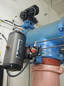
The solenoid valve (small black box at the top of the photo) with input air line (small green tube) used to actuate a larger rack and pinion actuator (gray box) which controls the water pipe valve
Solenoid valves are also characterized by how they operate. A small solenoid can generate a limited force. An approximate relationship between the required solenoid force Fs, the fluid pressure P, and the orifice area A for a direct acting solenoid valve is:[3]
��=��=���24
where d is the orifice diameter. A typical solenoid force might be 15 N (3.4 lbf). An application might be a low pressure (e.g., 10 psi (69 kPa)) gas with a small orifice diameter (e.g., 3⁄8 in (9.5 mm) for an orifice area of 0.11 in2 (71 mm2) and approximate force of 1.1 lbf (4.9 N)).
If the force required is low enough, the solenoid is able to directly actuate the main valve. These are simply called Direct-Acting solenoid valves. When electricity is supplied, electrical energy is converted to mechanical energy, physically moving a barrier to either obstruct flow (if it is N.O.) or allow flow (if it is N.C.). A spring is often used to return the valve to its resting position once power is shut off. Direct-acting valves are useful for their simplicity, although they do require a large amount of power relative to other types of solenoid valves.[4]
If fluid pressures are high and orifice diameter is large, a solenoid may not generate enough force on its own to actuate the valve. To solve this, a Pilot-Operated solenoid valve design can be used.[1] Such a design uses the pressurized fluid itself to apply the forces required to actuate the valve, with the solenoid as a "pilot" directing the fluid (see subsection below). These valves are used in dishwashers, irrigation systems, and other applications where large pressures and/or volumes are desired. Pilot-operated solenoids tend to consume less energy than direct-action, although they will not work at all without sufficient fluid pressure and are more susceptible to getting clogged if the fluid has solid impurities.[4]
A direct-acting solenoid valve typically operates in 5 to 10 milliseconds. Pilot-operated valves are slightly slower; depending on their size, typical values range from 15 to 150 milliseconds.[2]
Power consumption and supply requirements of the solenoid vary with application, being primarily determined by fluid pressure and orifice diameter. For example, a popular 3⁄4-inch 150 psi sprinkler valve, intended for 24 VAC (50–60 Hz) residential systems, has a momentary inrush of 7.2 VA, and a holding power requirement of 4.6 VA.[5] Comparatively, an industrial 1⁄2-inch 10,000 psi valve, intended for 12, 24, or 120 VAC systems in high-pressure fluid and cryogenic applications, has an inrush of 300 VA and a holding power of 22 VA.[6] Neither valve lists a minimum pressure required to remain closed in the unpowered state.
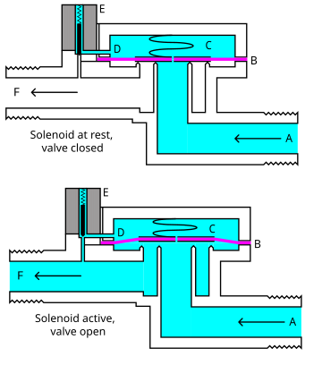
A- Input side
B- Diaphragm
C- Pressure chamber
D- Pressure relief passage
E- Electro Mechanical Solenoid
F- Output sidePilot-operated
[edit]While there are multiple design variants, the following is a detailed breakdown of a typical pilot-operated solenoid valve. They may use metal seals or rubber seals, and may also have electrical interfaces to allow for easy control.
The diagram to the right shows the design of a basic valve, controlling the flow of water in this example. The top half shows the valve in its closed state. An inlet stream of pressurized water enters at A. B is an elastic diaphragm and above it is a spring pushing it down. The diaphragm has a pinhole through its center which allows a very small amount of water to flow through. This water fills cavity C so that pressure is roughly equal on both sides of the diaphragm. However, the pressurized water in cavity C acts across a much greater area of the diaphragm than the water in inlet A. From the equation �=�∗�
, the force from cavity C pushing downward is greater than the force from inlet A pushing upward, and the diaphragm remains closed.
Diaphragm B will stay closed as long as small drain passage D remains blocked by a pin, which is controlled by solenoid E. In a normally closed valve, supplying an electric current to the solenoid will raise the pin via magnetic force, and the water in cavity C drains out through passage D faster than the pinhole can refill it. Less water in cavity C means the pressure on that side of the diaphragm drops, proportionately dropping the force too. With the downward force of cavity C now less than the upward force of inlet A, the diaphragm is pushed upward, thus opening the valve. Water now flows freely from A to F. When the solenoid is deactivated and passage D is closed, water once again accumulates in cavity C, closing the diaphragm once the downward force exerted is great enough.
This process is the opposite for a normally open pilot-operated valve. In that case, the pin is naturally held open by a spring, passage D is open, and cavity C is never able to fill up enough, pushing open diaphragm B and allowing unobstructed flow. Supplying an electric current to the solenoid pushes the pin into a closed position, blocking passage D, allowing water to accumulate in cavity C, and ultimately closing diaphragm B.
In this way, a pilot-operated solenoid valve can be conceptualized as two valves working together: a direct-acting solenoid valve which functions as the "brain" to direct the "muscle" of a much more powerful main valve which gets actuated pneumatically or hydraulically. This is why pilot-operated valves will not work without a sufficient pressure differential between input and output, the "muscle" needs to be strong enough to push back against the diaphragm and open it. Should the pressure at the output rise above that of the input, the valve would open regardless of the state of the solenoid and pilot valve.
Components

Example core tubes. Non-magnetic core tubes are used to isolate the fluid from the coil. The core tube encloses the plugnut, the core spring, and the core. The coil slips over the core tube; a retaining clip engages the depression near the closed end of the core tube and holds the coil on the core tube.
Solenoid valve designs have many variations and challenges.
Common components of a solenoid valve:[7][8][9][10]
- Solenoid subassembly
- Retaining clip (a.k.a. coil clip)
- Solenoid coil (with magnetic return path)
- Core tube (a.k.a. armature tube, plunger tube, solenoid valve tube, sleeve, guide assembly)
- Plugnut (a.k.a. fixed core)
- Shading coil (a.k.a. shading ring)
- Core spring (a.k.a. counter spring)
- Core (a.k.a. plunger, armature)
- Core tube–bonnet seal
- Bonnet (a.k.a. cover)
- Bonnet–diaphragm–body seal
- Hanger spring
- Backup washer
- Diaphragm
- Bleed hole
- Disk
- Valve body
- Seat
The core or plunger is the magnetic component that moves when the solenoid is energized. The core is coaxial with the solenoid. The core's movement will make or break the seals that control the movement of the fluid. When the coil is not energized, springs will hold the core in its normal position.
The plugnut is also coaxial.
The core tube contains and guides the core. It also retains the plugnut and may seal the fluid. To optimize the movement of the core, the core tube needs to be nonmagnetic. If the core tube were magnetic, then it would offer a shunt path for the field lines.[11] In some designs, the core tube is an enclosed metal shell produced by deep drawing. Such a design simplifies the sealing problems because the fluid cannot escape from the enclosure, but the design also increases the magnetic path resistance because the magnetic path must traverse the thickness of the core tube twice: once near the plugnut and once near the core. In some other designs, the core tube is not closed but rather an open tube that slips over one end of the plugnut. To retain the plugnut, the tube might be crimped to the plugnut. An O-ring seal between the tube and the plugnut will prevent the fluid from escaping.
The solenoid coil consists of many turns of copper wire that surround the core tube and induce the movement of the core. The coil is often encapsulated in epoxy. The coil also has an iron frame that provides a low magnetic path resistance.
Materials
[edit]The valve body must be compatible with the fluid; common materials are brass, stainless steel, aluminum, and plastic.[12]
The seals must be compatible with the fluid.
To simplify the sealing issues, the plugnut, core, springs, shading ring, and other components are often exposed to the fluid, so they must be compatible as well. The requirements present some special problems. The core tube needs to be non-magnetic to pass the solenoid's field through to the plugnut and the core. The plugnut and core need a material with good magnetic properties such as iron, but iron is prone to corrosion. Stainless steels can be used because they come in both magnetic and non-magnetic varieties.[13] For example, a solenoid valve might use 304 stainless steel for the body, 305 stainless steel for the core tube, 302 stainless steel for the springs, and 430 F stainless steel (a magnetic stainless steel[14]) for the core and plugnut.[1]
Types
Many variations are possible on the basic, one-way, one-solenoid valve described above:
- one- or two-solenoid valves;
- direct current or alternating current powered;
- different number of ways and positions;
Common use
Solenoid valves are used in fluid power pneumatic and hydraulic systems, to control cylinders, fluid power motors or larger industrial valves. Automatic irrigation sprinkler systems also use solenoid valves with an automatic controller. Domestic washing machines and dishwashers use solenoid valves to control water entry into the machine. They are also often used in paintball gun triggers to actuate the CO2 hammer valve. Solenoid valves are usually referred to simply as "solenoids."
Solenoid valves can be used for a wide array of industrial applications, including general on-off control, calibration and test stands, pilot plant control loops, process control systems, and various original equipment manufacturer applications.[15]
History and commercial development
Feedback Form x - Solenoid subassembly
-
BRASS FITTINGS
Brass fittings are
- An essential part of any plumbing system.
- Providing reliable seal connections between pipes.
- Valves.
- Other apparatus.
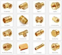
Brass is commonly used for industrial and household plumbing because of its durability, corrosion resistance, and long-lasting performance. Several brass fittings are available for different applications and purposes, ranging from tees, couplings, elbows, adaptors, plugs, unions, and wyes. This post will discuss each type in detail to help you understand which is most suitable for your plumbing project.
Types of Brass Fittings
Tees
Tees are brass fittings shaped like a ‘T’ when viewed from the side. They have three openings, two of which are positioned at a right angle to each other, and the third opening is set straight. Tees are typically used to connect three pipes at once, allowing the flow of fluids to be diverted or mixed within the piping system. They are commonly used in irrigation, central heating, and HVAC systems.
Couplings
A coupling is a brass fitting that connects two pipes end to end, allowing them to collaborate and transmit fluids efficiently. Collars come in different sizes and are used to join pipes of the same diameter or reduce the size of one line to connect to another. Couplings are straightforward to install and provide a reliable and tight seal between two sequences.
Elbows
Elbows are fittings bent at a 90-degree- or 45-degree angle, allowing pipes to change directions without creating challenging bends or curves in the plumbing system. Elbows are used to change the direction of the flow of fluids or direct the flow around obstacles, such as beams or columns. Elbows come in different angles, from 45 to 90 degrees, and are commonly used in drainage and plumbing systems.
Adaptors
Adaptors are brass fittings that connect different pipe sizes or types. They are used when the two pipes in the plumbing system have different sizes or when one pipe material transitions to another. Adaptors come in different shapes and sizes and can be threaded or slip-on. They are used in various plumbing applications, such as swimming pools, water filtration, and sprinkler systems.
Plugs
Plugs are fittings used to temporarily seal off a pipe opening. They are inserted into the pipe fitting to block the flow of fluids and prevent leaks when the pipework is under maintenance or repair. Plugs come in different sizes and shapes, such as hex plugs, square head plugs, or countersunk plugs, and they are usually made of brass or stainless steel.
Unions
A union is a brass fitting used to connect pipes but allows for straightforward disconnection without cutting or removing any part of the pipework. Blocks are constructed of two parts that screw together to form a tight seal. They make it easy to service or replace a section of the pipework without affecting other parts of the system. Unions are commonly used in gas piping, hydraulic lines, and marine applications.
Wyes
A wye is a brass fitting that splits the pipe flow in two directions. It has a Y-shaped configuration, with two equal-sized openings and one smaller opening at a 45-degree angle. Wyes are used in plumbing systems that disperse fluids or gases in two directions. They are commonly used in gutter systems, vent pipes, and sewage lines.
Feedback Form x -
AIR BLOW GUN DG 10
.jpg)
Air Blow Guns Information
Air blow guns attach to air lines for the manual actuation and/or control of air discharge. They are used primarily for:
- debris removal and purging
- non-contact part cleaning and drying
- general laboratory or industrial applications
Most air blow guns are made of plastic or metal and include an ergonomic grip or handle. A steady stream of compressed air is delivered through a sturdy metallic nozzle. Air blow guns that are equipped with an internal fail-safe pressure mechanism shut off automatically if the gun is dropped or the lip is blocked. Integral pressure relief valves are used to blow off excess pressure before discharge. In the United States, products that meet or exceed standards from the Occupational Safety and Health Administration (OSHA) are commonly available. Typically, manufacturers indicate whether products are suitable for high volume applications, or include a threaded discharge port or vacuum attachment.
Specifications
Specifications for air blow guns include pressure capacity and air line connection type. Pressure capacity, or maximum rated pressure, is rated at the air inlet and measured in pounds per square inch (psi). Many types of air line connectors are available. Quick-release connectors contain fittings that are attached internally. By contrast, push-on connectors include barbed ferrules. Air blow guns use several types of national pipe thread (NPT) connectors, most of which are inch-based and female. Important NPT measurements include threads per inch (TPI) and outside diameter (OD):
- 1/8 in. NPT connectors have 27 TPI and an OD of 0.405 in.
- 1/4 in. NPT connectors have 18 TPI and an OD of 0.540 in.
- 3/8 in. NPT connectors also have 18 TPI, but an OD of 0.675 in.
- 1/2 in. connectors have 14 TPI and an OD of 0.840 in.
#10-32 NPT threads are also available. Air line connections that can swivel or pivot are suitable for applications that require versatile positioning.
Types
Air blow guns vary in terms of nozzle type and actuation style. Standard safety nozzles are suitable for general-purpose applications. Small-diameter nozzles can be inserted into tight openings. Nozzles with rubber tips prevent the marring of surfaces while nozzles with flexible tips can be guided directly to the application point. Air blow guns with extended, straight nozzles provide longer reach. Devices with extended, angled nozzles are designed for use in difficult-to-reach locations. Venturi nozzles contain small holes that allow the discharge to draw ambient air to increase the airflow. Air screens are often used to minimize particle blowback. In terms of actuation, most air blow guns include a discharge lever that is in-line with the air hose and actuated by the thumb. Pistol or trigger-style devices are also available. With these devices, the actuator is located at a right-angle to the air supply hose and incorporates an ergonomic handle. Button-actuated air blow guns are also available.
Feedback Form x -
FILTER REGULATOR LUBRICATOR
What is an FRL unit
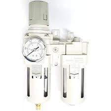
An FRL unit comprises a filter (F), regulator (R), and lubricator (L). These individual units can combine into one unit to ensure clean air in a pneumatic system. It is also possible to use each component individually. A proper air filter, regulator, and lubricator unit in a pneumatic system provides higher reliability of the components downstream, reduced power wastage from over-pressurization, and increased component lifetime. The three components in an FRL unit work together.
- Filters: Filters remove water, dirt, and other harmful debris from an air system, which is often the first step in improving air quality.
- Regulators: The second step in an FRL system is a regulator. Regulators adjust and control the air pressure of a system to ensure that down-line components do not exceed their maximum operating pressures.
- Lubricators: Lubricators reduce the internal friction in air tools by releasing a controlled oil mist into the compressed air. This is often done last and/or right before the component that needs lubrication.What FRL components are necessary?
Filter, regulator, and lubricators are available individually or as a combined air filter-regulator (FR) or filter-regulator-lubricator (FRL) unit. Install an air compressor filter and regulator unit if the equipment is self-lubricating and an FRL unit if the equipment requires lubrication.
It is essential to understand the air requirements of the system and components to determine the selection of individual components of an FRL unit for an application. The FRL components necessary depends on the system requirements. However, ensure that every air system uses at least one filter and one pressure regulator. Most modern pneumatic tools use self-lubricating seals, and the user often does not need to install a separate lubricator. If a tool isn’t self-lubricating, also install a lubricator in the system. As a general rule, a pneumatic system’s order of installment is: a compressor, filter, regulator, and lubricator. Give careful consideration to the order and location of these devices.
Application specifications
Before selecting an FRL unit, it is important to consider a few system parameters:
- pressure
- flow rate
- air quality requirements of the tools using compressed air
- if any air quality standards apply to the workplace
To ensure that the FRL unit, or one of its components, meets the pressure ranges in and out of the flow rate requirement (typically in liters per min), consult the datasheet for the specific unit.
Consider the environment around the device. Housings come in different materials to accommodate different environmental conditions.
- Choose a metal housing if the device is outside and exposed to heat, salt water, salt air, or chemicals.
- Use Nylon or polycarbonate housing for most general applications.
Read our chemical resistance guide for more details on the material compatibility for each application.
Pneumatic filter selection
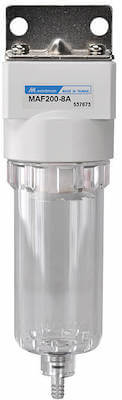
Figure 2: Pneumatic filter
Filters remove water, dirt, and other harmful debris from an air system (Figure 2). Two factors determine a filter’s necessary micron size and bowl material: contaminants’ type and size and components’ air requirements. Common applications typically require a filter rated between 5 - 40 microns. The filter rating gives the particle size limit that the filter allows to pass through. For example, a 20-micron filter allows only particles smaller than 20 microns to pass through.
Filters experience a slight pressure drop across the inlet and outlet ports due to flow restriction. Because it’s easier for contaminants to clog a 0.1-micron filter than a 40-micron filter, 0.1-micron filters create a higher pressure drop and require more maintenance. Therefore, do not oversize the filter by selecting the finest micron size, as it can lead to higher costs for the component, a larger pressure drop, and more maintenance time. Instead, choose a filter that will remove only the smallest contaminant specific to your system.
The bowl material and drainage type are also necessary to get right. The bowl comes into contact with the contaminants and houses the filtered particles. Therefore, the pressure, temperature, and chemicals present affect the bowl material selection. Filters also require drainage using an automatic, semi-automatic or manual drainage system. Or a condensate drain can attach to the outlet to remove the filtered contaminants.
- Automatic: An automatic drain is a 2/2-way valve that closes upon system pressurization. It has a float system that rises upon system depressurization or liquid accumulation. The float rising causes the drain to open. Choose automatic drainage when the equipment is in continual use, requires frequent drainage, or is in a hard-to-reach location.
- Semi-automatic: A semi-automatic drain automatically drains the system upon depressurization. It can drain a pressurized system, but only manually. Use a semi-automatic drainage filter if the system is only sometimes under pressure.
- Manual: It is possible to manually drain a filter in a depressurized system. However, do not choose manual drainage if the location is in a hard-to-reach location, the system requires frequent drainage, or the application doesn’t depressurize the system regularly.
- Condensate Drain: A condensate drain attaches to the filter’s outlet and drains it. However, ensure to set the opening/closing timings.
Pneumatic pressure regulator selection
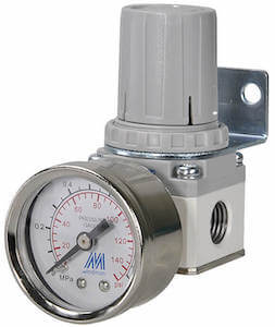
Figure 3: Pneumatic pressure regulator
Pressure regulators, also called pressure-reducing valves, adjust and control the system's air pressure to limit downstream pressure and protect downstream components. (Figure 3). Two of the most critical selection criteria for pressure regulators are the pressure rating and if it is a relieving or non-relieving regulator.
- Pressure rating: It is essential to include a safety factor on the maximum input pressure so that the regulator can handle excess pressure. In standard pressure regulators, a manual knob sets the output pressure. Typically, a regulator’s manual will have a flow curve that allows a user to correctly size a regulator based on the system flow rate and desired outlet pressure. Regulators also provide a consistent and stable outlet pressure. To regulate the pressure to 0.6 MPa, select a regulator having a maximum range of 1 MPa instead of 0.7 MPa to ensure that it does not damage the regulator if the system becomes over-pressurized. In addition, if the inlet pressure is too high for a single device, two pressure regulators in a row can be used to decrease the pressure in two stages.
- Relieving or non-relieving regulators: Relieving regulators have a built-in vent that lets excess pressure escape once it exceeds a certain threshold. Non-relieving regulators will not vent this extra pressure and rely on a secondary device to decrease pressure. For a non-toxic application, use a relieving regulator to ensure that a buildup in pressure doesn’t occur and cause damage. However, when the application consists of dangerous or expensive gasses, do not release them into the atmosphere.
Pneumatic lubricator selection
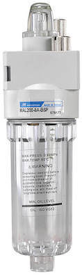
Figure 4: Pneumatic lubricator
Lubricators reduce the internal friction in tools or equipment by releasing a controlled oil mist into the compressed air (Figure 4). Knowing the pneumatic component’s need for lubrication will determine the oil type and drip rate (the amount of oil released downstream). There are two types of lubricators.
- Oil-fog: Oil-fog lubricators supply 100% of the oil seen in the sight glass downstream as a large droplet. It is suitable for short distances and typically just for one component requiring heavy lubrication.
- Micro-fog: Micro-fog lubricators supply roughly 10% of the oil seen in the sight glass downstream as a mist (< 2 µm). These lubricators are suitable for long distances and multiple components.
Lubricator maintenance is refilling the oil reservoir. Monitor the oil level through the sight glass or a window on the housing. Lubricators also need a pressure differential to make the oil drip. Therefore, they create a pressure drop at the outlet. Take this into account to ensure the proper pressure reaches the end component. This means the air will not be lubricated if the system is off, preventing oil wastage. Read our article on oiling pneumatic tools for more details on the different types of oil used in pneumatic systems and their selection criteria.
Feedback Form x -
ALUMINIUM FITTINGS
.jpeg)
Aluminum Pipe Fittings are components used to connect pipes or tubes. They join two pieces of piping, allowing them to be rotated around their inside diameter and secured by tightening the appropriate fastener. They come in various sizes, shapes and materials, with aluminium being one of the most common due to its strength, lightweight nature and corrosion resistance. These features make it an ideal choice for those needing a durable yet affordable material for pipe fittings.
Properties of Aluminum Pipe Fittings
Aluminium pipe fittings are lightweight, corrosion-resistant and durable metal components commonly used to join two pipe or tube sections. They offer outstanding temperature resistance and strength, making them ideal for industrial applications and machinery construction. Additionally, aluminium pipe fittings have superior fire protection capabilities to other metals due to their strong anti-oxidant nature. In terms of cost, aluminium is generally more affordable than its counterparts, such as steel or copper, which makes it an economical option for many projects. Finally, aluminium pipe fittings are easily available in various sizes and shapes, allowing maximum flexibility when designing your product or installation.
Characteristics of Aluminum Pipe Fittings
Aluminium pipe fittings are popular due to their corrosion resistance, affordability, and lightweight nature. They can be used in many applications, such as plumbing, HVAC systems, air conditioning units, and industrial piping systems. Not only do they have excellent chemical resistance properties against water and other liquids, but they also provide insulation against sound and thermal radicalization. Additionally, aluminium pipe fittings feature high-temperature ranges (up to 500°F), making them great for use in environments with extreme temperatures, like aerospace industries or areas near the equator.
Applications of Aluminum Pipe Fittings
Aluminium pipe fittings can be used in a wide range of applications. In plumbing, aluminium joins pipes using solvent cement or threads. Many industries commonly use aluminum for irrigation and water service lines, gas pipe pipelines, refrigeration systems, and air-conditioning systems. Its lightweight nature makes it easier to handle than traditional metals like copper and steel. Moreover, aluminium is corrosion-resistant and has a longer lifespan than other materials.
Types of Aluminum Pipe Fittings
Aluminium pipe fittings are available in different types, like elbows, reducers, tees, couplings, caps, and flanges. Elbows are fittings that change the direction of the pipe by 45 or 90 degrees. Reducers or bushings are used to connect two pipes of different sizes, while tees are used to connect three pipes at right angles. Couplings are used to connect two pipes without changing their direction. Caps are used to close the pipe’s end, while flanges connect the piping system to pumps, valves, and other equipment.
Advantages of Aluminum Pipe Fittings
Aluminium pipe fittings offer advantages like easy installation, low weight, excellent thermal conductivity, high strength-to-weight ratio, and corrosion resistance. They have a low maintenance cost and can be recycled at the end of their life, making them a sustainable choice. Aluminium fittings are also highly customizable, offering a range of shapes, sizes, and finishes to fit specific applications.
Conclusion:
Aluminium pipe fittings have become popular for various applications, from residential plumbing to industrial oil and gas operations. They offer several unique properties, characteristics, and advantages, making them an ideal choice for these applications. We hope you found this blog post informative and useful in understanding the properties and applications of aluminium pipe fittings. In summary, aluminium pipe fittings offer an excellent combination of strength, lightness, and sustainability, making them an ideal choice for any project that requires a robust and reliable piping system.
Feedback Form x -
Pneumatic fittings
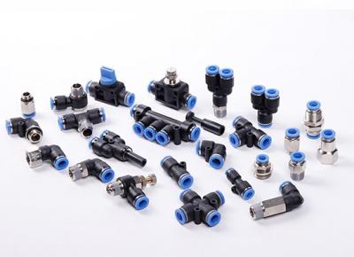
Pneumatic fittings are components used in pneumatic pressurized gas systems to join pipe, tube, and hose sections. Tighter seals distinguish pneumatic fittings and reduced pressure needs as compared to hydraulic fittings. They’re often found in pneumatic logic control and instrumentation systems.
Pneumatic pipe fittings exist in various forms and sizes, and their connection types and purposes vary. However, because of the close connection between the uses and applications of these components, more attention will be paid to the kinds of pneumatic fittings based on function. Some pneumatic fittings add or change direction, while others join smaller pipes, and still, others are only intended for specific connections or purposes, depending on their functions.
Application of Pneumatic Fittings
Application of Pneumatic fittings isn’t only for usage in industries. All you have to do is glance around, and you’ll see them all around. We use pneumatic fittings in a variety of situations in our everyday lives.
Pneumatic fittings may be found in a variety of items that we use daily, including:
Bicycle/ball pumps
Tire pressure gauges
Some nail guns
The handicapped-access buttons which operate automatic doors
Vacuum cleaners
Some car shocks
Uses of Pneumatic Fitting
Production Lines
Today, these systems and fittings are used in a broad range of sectors and applications, including construction, assembly, production line settings, and a wide range of industrial machines, handheld tools, and workstation equipment. A pneumatic fittings versatility, reliability, cost-effectiveness, and safety may frequently outperform a comparable arrangement driven by different electric motors and actuators in many industrial environments.
Control of Airflow
Pneumatic fittings are the vital connection between tubes, hoses, and other pneumatic system components. Air fittings have tighter seals and needless pressure than hydraulic fittings and are usually available in various connection types. Miniature fittings regulate airflow pressure and directional flow, connect pneumatic fittings, and halt unused ports’ flow.
Energy Consumption
Although pneumatic coupler is the smallest component of the total pneumatic system design, they are arguably the most essential. Pneumatic fittings, together with their pipes, hoses, and tubes, link all of the other main components and, therefore, have a significant impact on the system’s overall efficiency, safety, and energy consumption.
Because pneumatic pipe fittings are in charge of sending the correct quantity of compressed air where it needs to go, choosing the appropriate one is critical. As a result, there is a huge range of sizes and forms. Straight fittings and elbow fittings are common, as are more complicated cross fittings, branch fittings, valves, and other items. Air fittings are characterized by their compression technique, how they join, material make-up, and how they are barbed in addition to their overall form or purpose.
When choosing new pneumatic pipe fittings, all of these variables must be considered to guarantee the most significant possible connection and long-term performance. Applications suffer from decreased power, torque, and efficiency without the appropriate pneumatic fittings, thus negating the advantage of pneumatic systems in the first place.
Feedback Form x -
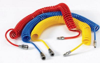
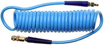
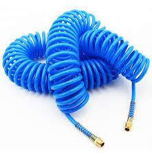
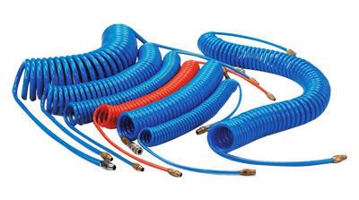
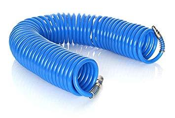
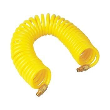
PU COILED HOSE
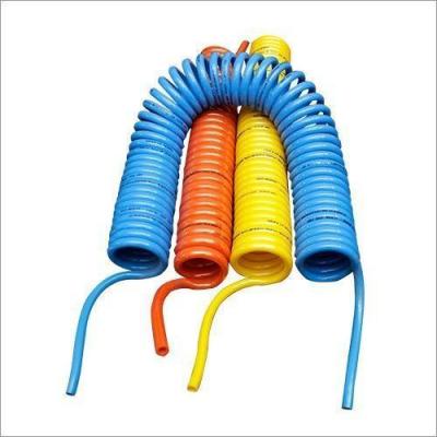
PU coiled hoses, also known as spiral hoses, are commonly used in pneumatic systems. Their coiled design allows for flexibility and easy storage. They are often used to connect air tools to compressors.
Here's what I could gather about Adhikari PU Coiled Hoses:
- Material: Made from polyurethane, known for its flexibility, durability, and resistance to abrasion.
- Usage: Primarily used for pneumatic applications, such as connecting air tools, in robotics, and automated machinery.
- Features: Coiled design for flexibility and easy storage, various sizes available.
- Availability: You can likely find Adhikari PU Coiled Hoses at industrial supply stores or by contacting Adhikari Industries directly. You may also find them through online retailers.
When inquiring about Adhikari PU Coiled Hoses, it would be helpful to specify:
- Size and diameter: The inner and outer diameter of the hose you need.
- Length: The desired length of the coiled hose.
- Pressure rating: The maximum pressure the hose needs to withstand.
- Application: What you intend to use the hose for.
Feedback Form x -
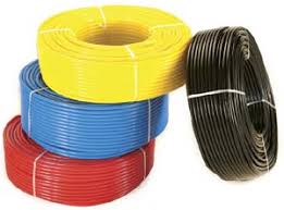
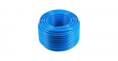
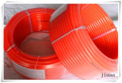
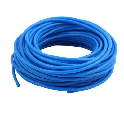
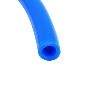
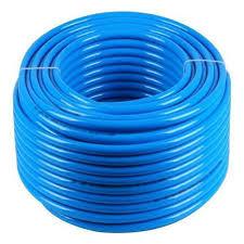
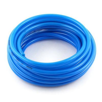
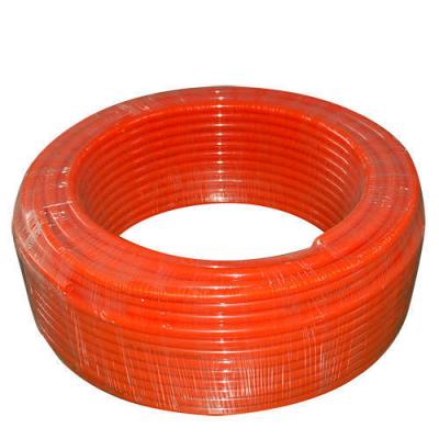
PU TUBES
What are PU Tube Rolls?
- PU stands for Polyurethane. It's a versatile material known for its flexibility, durability, and resistance to abrasion.
- Tube rolls refer to long lengths of tubing made from polyurethane, coiled and packaged for easy storage and use.
Common Uses of PU Tube Rolls:
- Pneumatic Systems: PU tubing is widely used in pneumatic systems to carry compressed air for various applications, such as powering tools and machinery.
- Air Tools: They are ideal for connecting air tools to compressors due to their flexibility and ability to withstand pressure.
- Robotics and Automated Machinery: PU tubes are used in robotics and automated systems for their flexibility and resistance to wear and tear.
- Fluid Transfer: Depending on the specific type of PU tubing, it can also be used for transferring various fluids.
Key Features of PU Tube Rolls:
- Flexibility: PU tubing is highly flexible, allowing for easy installation in tight spaces and around obstacles.
- Durability: Polyurethane is a strong material that can withstand pressure and resist abrasion, ensuring a long lifespan for the tubing.
- Variety of Sizes: PU tube rolls are available in various sizes to suit different applications and flow requirements.
- Convenient Packaging: The rolls make it easy to store and dispense the tubing, minimizing waste and maximizing efficiency.
Where to Find PU Tube Rolls:
You can find PU tube rolls at industrial supply stores, online retailers like Amazon, and from specialized manufacturers of pneumatic and fluid transfer products.
When choosing PU tube rolls, consider the following factors:
- Size and diameter: Select the appropriate size and diameter based on your specific application and flow requirements.
- Pressure rating: Ensure the tubing can handle the pressure of your system.
- Temperature range: Check the temperature range to ensure the tubing is suitable for your operating environment.
- Material compatibility: If you're using the tubing for fluid transfer, make sure the PU material is compatible with the fluids you'll be using.
If you have any specific questions about PU tube rolls or need help finding the right product for your needs, feel free to ask!
Feedback Form x -
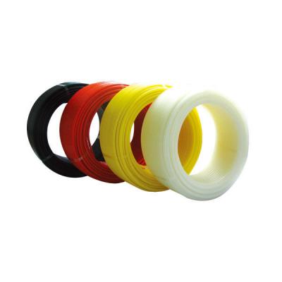
ADHIKARI ROUND CORD
PU round cord refers to a type of cord made from polyurethane (PU) that has a round cross-section. Polyurethane is a versatile material known for its durability, flexibility, and resistance to abrasion, chemicals, and weathering. These properties make PU round cords suitable for various applications across different industries.
Key features and benefits:- High tensile strength: PU round cords can withstand significant pulling forces without breaking, making them suitable for applications where strength is crucial.
- Excellent abrasion resistance: PU is highly resistant to wear and tear, making these cords ideal for applications involving friction or contact with rough surfaces.
- Good flexibility: PU round cords can bend and flex without kinking or losing their shape, allowing for use in dynamic applications.
- Chemical resistance: PU is resistant to many chemicals, oils, and solvents, making these cords suitable for harsh environments.
- Weather resistance: PU can withstand exposure to sunlight, ozone, and other environmental factors without degrading, making these cords suitable for outdoor use.
Common applications:
- Power transmission: PU round cords are often used as drive belts in machinery and equipment, transferring power between rotating shafts.
- Conveying: PU round cords can be used in conveyor systems to move materials or products along a production line.
- Sealing: PU round cords can be used as seals or gaskets to prevent leakage in various applications.
- Vibration dampening: PU round cords can be used to absorb vibrations and reduce noise in machinery or equipment.
- Elastic elements: PU round cords can be used as elastic elements in various mechanisms, providing flexibility and cushioning.
Choosing the right PU round cord:
When selecting a PU round cord, consider the following factors:
- Diameter: The diameter of the cord will determine its strength and flexibility.
- Hardness: The hardness of the PU material will affect the cord's stiffness and resistance to deformation.
- Tensile strength: The tensile strength of the cord should be sufficient for the intended application.
- Operating temperature: The cord should be able to withstand the temperature range of the application.
- Chemical compatibility: The cord should be compatible with any chemicals it will come into contact with.
Feedback Form x -
PU ROUND CORD
PU round cord refers to a type of cord made from polyurethane (PU) that has a round cross-section. Polyurethane is a versatile material known for its durability, flexibility, and resistance to abrasion, chemicals, and weathering. These properties make PU round cords suitable for various applications across different industries.
Key features and benefits:- High tensile strength: PU round cords can withstand significant pulling forces without breaking, making them suitable for applications where strength is crucial.
- Excellent abrasion resistance: PU is highly resistant to wear and tear, making these cords ideal for applications involving friction or contact with rough surfaces.
- Good flexibility: PU round cords can bend and flex without kinking or losing their shape, allowing for use in dynamic applications.
- Chemical resistance: PU is resistant to many chemicals, oils, and solvents, making these cords suitable for harsh environments.
- Weather resistance: PU can withstand exposure to sunlight, ozone, and other environmental factors without degrading, making these cords suitable for outdoor use.
Common applications:
- Power transmission: PU round cords are often used as drive belts in machinery and equipment, transferring power between rotating shafts.
- Conveying: PU round cords can be used in conveyor systems to move materials or products along a production line.
- Sealing: PU round cords can be used as seals or gaskets to prevent leakage in various applications.
- Vibration dampening: PU round cords can be used to absorb vibrations and reduce noise in machinery or equipment.
- Elastic elements: PU round cords can be used as elastic elements in various mechanisms, providing flexibility and cushioning.
Choosing the right PU round cord:
When selecting a PU round cord, consider the following factors:
- Diameter: The diameter of the cord will determine its strength and flexibility.
- Hardness: The hardness of the PU material will affect the cord's stiffness and resistance to deformation.
- Tensile strength: The tensile strength of the cord should be sufficient for the intended application.
- Operating temperature: The cord should be able to withstand the temperature range of the application.
- Chemical compatibility: The cord should be compatible with any chemicals it will come into contact with.
Feedback Form x -
ADHIKARI PU COILED HOSE
Note :- Discount Applicable as par oder, velue...........
huc999.casinoSIZE
3MTR
5MTR
10MER
15MTR
4x6
110
185
370
570
5x8
150
250
500
750
5.5x8
148
245
490
745
6x8
138
225
450
680
8x10
170
290
580
880
6.5x10
200
340
680
1050
8x12
250
415
830
1245
10x14
340
560
1120
1700
12x16
360
600
1200
1810
Feedback Form x -
APSOO PU TUBING ROLLS
Discount Applicable as par oder, velue
http://www.adhikariindustries.in
krooree.comSIZE(IDxOD mm)
MTR.(ROLL)
PRICE
2.5x4
100/200
8.8
4x6
100/200
15.6
6x8
50/100
22.8
5.5x8
50/100
24.5
5x8
50/100
27.6
6.5x10
50/100
41.3
8x10
50/100
33.2
10x12
50/100
41.2
9x12
50/100
49.3
8x12
50/100
55.8
10x14
50/100
79.4
12x16
50/100
97.4
Feedback Form x -
APSOO PU TUBING ROLLS
NOTE : -DISCONTS AS FOR PAR ODER VELUES...............
kuyuluk.comSIZE(IDxOD mm)
MTR.(ROLL)
PRICE
2.5x4
100/200
8.8
4x6
100/200
15.6
6x8
50/100
22.8
5.5x8
50/100
24.5
5x8
50/100
27.6
6.5x10
50/100
41.3
8x10
50/100
33.2
10x12
50/100
41.2
9x12
50/100
49.3
8x12
50/100
55.8
10x14
50/100
79.4
12x16
50/100
97.4
Feedback Form x -
APSOO PU COILED HOUSE
Note :- Discount Applicable as par oder, velue
soccer918.comSIZE
3MTR
5MTR
10MER
15MTR
4x6
87
140
280
440
5x8
125
210
420
640
5.5x8
120
200
400
610
6x8
115
190
380
580
8x10
145
240
480
730
6.5x10
170
280
560
850
8x12
220
360
720
1140
10x14
340
560
1120
1700
12x16
360
600
1200
1810
Feedback Form x -
NYLON TUBING ROLLS
Discount Applicable as par oder, velue
http://www.adhikariindustries.in
thaibet55.comSIZE(IDxOD mm)
MTR.(ROLL)
PRICE
WORKING PRESSURE KG/cm2
2.5
30/50/100
9.4
25
4x2
30/50/100
9.8
35
54.7x2.7
30/50/100
10.8
40
6x4
30/50
14.3
20
5x3
30/50
11.8
30
6.35x4.35
30/50
15.3
20
8x5
30/50/100
22.2
35
8x6
30/50/100
18.3
20
9.5x7.5
30/50/100
23.7
20
10x8
30/50
27.7
15
12x9
30/50
38.6
18
12x10
30
36.7
12
14x12
30
53.6
15
Feedback Form x -
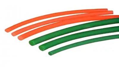
PU Round Cord
NOTE:- Discounts Applicable as par Order value ..
metungtech.comSIZE(IDxOD mm)
MTR.(ROLL)
PRICE SMOOTH (ORANGE)
PRICE ROUGH(GREEN)
3
50/100
12.7
18
4
50/100
15.7
22.5
5
50/100
25.4
35
6
50/100
29.5
46.5
8
50/100
71.3
88.5
10
50/100
107
137
12
50/100
145.5
190
Feedback Form x -
PU Tubing Rolls
Discount Applicable as par oder, velue
http://www.adhikariindustries.in
slot938.comSIZE(IDxOD mm)
MTR.(ROLL)
PRICE
WORKING PRESSURE KG/cm2
2.5x4
100
11
13
2x4
100
12.2
15
4.3x2.9
100
11.3
13
4x6/6.35/4.35
100
16.8
15
5.5x8/8.3x5.9
50/100
27.9
20
5x8
50/100
29.9
22
6x8
50/100
24.1
15
7x10
50/100
46.8
22
6.5x10
50/100
46.8
22
8x10
50/100
37
15
8x11
50/100
60.3
22
8x12
50/100
60.7
22
10x12
50/100
56
15
8x12
50/100
61.4
26
9.5x14
50/100
104
26
16x11
50/100
104
26
10x14
50/100
88
26
12x16
50/100
98
26
Feedback Form x -
PU Round Cord
PU round cord refers to a type of cord made from polyurethane (PU) that has a round cross-section. Polyurethane is a versatile material known for its durability, flexibility, and resistance to abrasion, chemicals, and weathering. These properties make PU round cords suitable for various applications across different industries.
Key features and benefits:- High tensile strength: PU round cords can withstand significant pulling forces without breaking, making them suitable for applications where strength is crucial.
- Excellent abrasion resistance: PU is highly resistant to wear and tear, making these cords ideal for applications involving friction or contact with rough surfaces.
- Good flexibility: PU round cords can bend and flex without kinking or losing their shape, allowing for use in dynamic applications.
- Chemical resistance: PU is resistant to many chemicals, oils, and solvents, making these cords suitable for harsh environments.
- Weather resistance: PU can withstand exposure to sunlight, ozone, and other environmental factors without degrading, making these cords suitable for outdoor use.
Common applications:
- Power transmission: PU round cords are often used as drive belts in machinery and equipment, transferring power between rotating shafts.
- Conveying: PU round cords can be used in conveyor systems to move materials or products along a production line.
- Sealing: PU round cords can be used as seals or gaskets to prevent leakage in various applications.
- Vibration dampening: PU round cords can be used to absorb vibrations and reduce noise in machinery or equipment.
- Elastic elements: PU round cords can be used as elastic elements in various mechanisms, providing flexibility and cushioning.
Choosing the right PU round cord:
When selecting a PU round cord, consider the following factors:
- Diameter: The diameter of the cord will determine its strength and flexibility.
- Hardness: The hardness of the PU material will affect the cord's stiffness and resistance to deformation.
- Tensile strength: The tensile strength of the cord should be sufficient for the intended application.
- Operating temperature: The cord should be able to withstand the temperature range of the application.
- Chemical compatibility: The cord should be compatible with any chemicals it will come into contact with.
Feedback Form x


FOLLOW US ON


